Hi there, welcome to my blog - La Revolution Deux. It's an odd name - but I like it! Here you will find all the info on my various DIY Guitar effects builds, amplifiers and guitars. Everything from a humble Ibanez tubescreamer to the holiest KLON Overdrive.
You may also find a few effects builds that I am looking to move on - usually in exchange for other effects/gear/cash. You can always check my ebay account to see what I've got up for grabs.
Have fun, enjoy the blog - Fred Briggs :-)
CONTACT ME
Feel free to get in contact with me about anything you see on this blog or with any general questions about guitars, amplifiers and effects, I'll be happy to answer! Just click the button above to email me directly or alternately my email address is fredbriggs2007 [at] googlemail [dot] com
This was one of my all time favourite pedals - the *harder to find than hen's teeth* Super Tube Screamer ST-9. I had it stolen many years ago and I've been looking out for a replacement ever since! But, no need now - the schematic is available thanks to the wonderous Dirk Hendrik :-D So we can all build ourselves one of these super rare beasts.
So what is the ST-9? It's basically an Ibanez 9 Series Tube Screamer with a "Mid Boost" control up in front.
Along with a hand sketched layout file (It's clear enough if you download it);
I would recommend this build to anyone who like Tube Screamer type overdrives - it's an absolute little cracker! For those of you who do attempt a build here's the freestompboxes.org forum topic which includes some useful info for you: http://freestompboxes.org/viewtopic.php?f=1&t=3536
*Note* - A lot of people mix the Super Tube Screamer ST-9 with the "STL Super Tube" which was a later spin off of the ST-9! Here's the "STL Super Tube";
The Ibanez Super Tube - not the same as the ST-9!
The STL Super Tube is almost the same electronically as the the ST-9, the only major difference being that the Mid Boost control is placed after the clipping stage rather than before it. Here's a schematic for the STL Super Tube;
Both pedals sound good and are certainly worth a build!
The Maxon OD-820 has been touted around the boutique world for many years as a "Klon Killer" supposedly able to do that pristine clean boost with a heap of overdrive in reserve. Not many people have seen the schematic and, while it's not a Klon, it does feature many of the same ideas.
Firstly here's the description from the Maxon website:
"While many consider the OD808 to be the greatest overdrive ever created, Maxon is not a company to rest on its laurels. Instead of basking in the glowing praise, Maxon has focused on the user's feedback to come up with an all-new overdrive circuit that addresses the key shortcomings of other units - the result is the OD-820 Overdrive Pro.
The OD-820 was designed to provide a wide range of tube-amp overdrive tones as well as a transparent, hi-gain clean boost. As the name implies, the OD-820 was intended for use by professional guitarists with advanced playing techniques. The OD-820's expressive tone reproduces fingering and picking nuances with haunting precision, making the best use of any guitar or amplifier's character. With a full-frequency response, minimal compression and zero tonal coloration, the OD-820 won't mask a player's performance weaknesses like other overdrives can.
One of the key ingredients to the OD-820's amazing sound lies in its power section. While the OD-820 accepts 9 volts coming in, it then uses a DC-DC voltage converter (#MAX1044) to bump this up to 18 volts. This higher voltage allows for a more accurate, full-frequency reproduction of the input signal than other units can provide. This higher voltage also allows for more balanced powering of the circuit, providing stabilized positive and negative DC voltage to the overdrive, blend, and tone sections of the circuit.
Overdrive and Blend? That's right the other secret weapon of the OD-820 lies in it's blending of distorted and non-distorted signal to create its massive tone. The OD-820's Drive knob does double duty, controlling both the amount of gain and the balance between distorted and non-distorted signal. Note that we said non-distorted signal rather than dry signal this is because this signal is still processed through the tone section of the OD-820's circuit before reaching the output. So, at the lowest Drive settings only non-distorted signal is sent to the output, providing the OD-820's stunning clean boost tone.
Like the OD808, the OD-820 distorts signal in the amplifier section of the circuit rather than having a separate clipping stage, which provides a smoother, more realistic tube-like overdrive than other methods. The higher voltage supplied to the amplifier section provides slightly more clipping than the OD808 or OD-9. The OD-820 uses only JRC4558 op amps for the warmest overdrive tone possible."
And the ProGuitarShop demo video:
And finally the schematic:
So, what have we got here. First up is a simple jfet buffer which preludes the gain control. Note that the gain control isn't actually adjusting the gain of the following opamp clipping stage it's channelling the signal between the clean blend path and the clipping opamp. What following is essentially a mixing stage for the clean signal and clipped signal. Next up is a third opamp stage - this is essentially a standard tubescreamer type tone control, nothing too special. The final opamp stage is just buffering up the volume control and keeping itself nicely out of the way ;-)
Also of note is the charge pump IC. Essentially what this is doing is providing the opamps with + and - 9VDC to ensure they run with the headroom necessary not to impart any of their own "hard rail" clipping (which usually sounds pretty bad!) on the signal.
In both electronic and aural terms the Maxon OD 820 is more transparent than the Klon Centaur - it doesn't impart the mid range texture that is a signature of the Klon. It does, however, sound just as good in it's own unique manner.
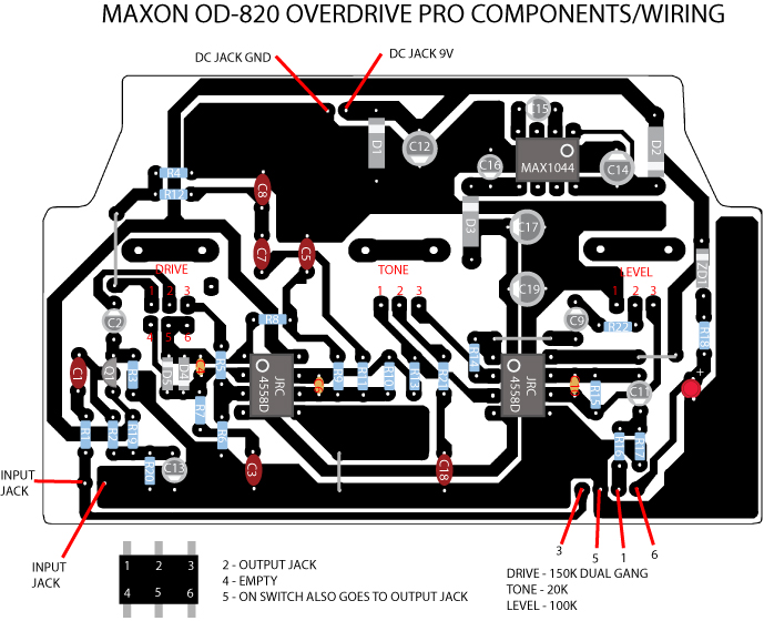
Here's a PCB layout and parts list (thanks to Dirk Hendrik and Bside2234);
Maxon Od 820 PCB Layout
Maxon OD 820 Parts List
Maxon OD 820 PCB Transfer
Note the parts list doesn't include part numbers for the diodes - sticking with 1N914/1N4148 would make sense as most of Maxon's overdrives go with this standard. However, other diodes are easily usable... Enjoy :-D
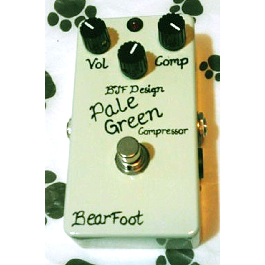
The Bearfoot FX Pale Green compressor - twin brother of the BJFe Pale Green compressor and close cousin of the Mad Professor Forest Green Compressor (Which is one of my favourite compression pedals!). Here's the description from the Bearfoot FX website:
"The BearFoot Pale Green Compressor is an exact replica of the BJFe Pale Green Compressor - the compressor for people who hate compressors !
The PGC really shines in a live situation with a band where the heavier handed compressors, that sound good at home in a room, often sound thick and lifeless against other real instuments....
This is no squish machine or infinite artificial sustainer ... The PGC is already famous for its nearly transparent compression and dead quiet operation. You will want to leave it on all the time... You will also wonder if its on at all ~ until you turn it off to make sure and then turn it back on as quickly as possible.
The middle knob fine tunes the EQ with a stacked pot that adjusts the EQ both pre and post compression. The zero point is at 'noon' ~ to the left it adjusts the EQ to that of the classic Dyna/Ross comps and to the right it allows an increase in treble and sparkle without adding noise or hiss. And with the comp knob off it is a booster/enhancer/EQ. Especially tasty into the Honey Bee and Model H.
Voltage range 8~18v."
And here's a demo video for you;
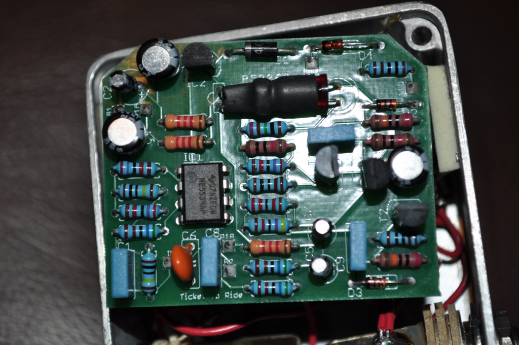
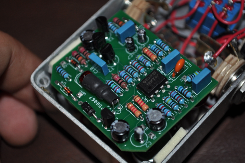
Well here's some Pale Green guts;
Looking at the guts it becomes clear that the Pale Green Compressor is a simlification of the Mad Professor Forest Green design;
So - the long and short of it? If you want a BJF designed compressor - build yourself a Mad Professor Forest Green Compressor ;-)
Live at LEEEEEEEEEDs! The Who - Live at Leeds is one of the best live albums ever recorded and one of the main reasons for this is Pete Townshends MASSIVE guitar tone created by his walls of super dynamic Hiwatt amps combined with a Univox SuperFuzz. Well - the Catalinbread "WIIO" pedal aims to give you the Hiwatt side of the equation and it does a damn good job of it too!
"Sheer raw power. Dynamics that feel like a roundhouse kick to the chest. Incredibly responsive clean up with the flick of the wrist. This is the WIIO.
The WIIO is an overdrive inspired by the powerfully unforgiving British amps from the ‘70s. Its all right there at your fingertips - your picking attack determines how much gain is delivered to the speakers. There is none of the typical compression found in most other overdrives to hide behind or to soften the blow - this is brass knuckle to the jaw type sonic impact we‘re talking here - you literally feel as though you plugged straight into the power section.
Like the amps, the WIIO has a wide freq spread so if your amp can deliver you’ll be rewarded with crisp clear highs and a very full tight low end. Lower gain settings are very clean and linear - you can hear every pick stroke and fingerprint, and the headroom allows for some very rich sounds when using modulation pedals. As you crank up the Gain the breakup is aggressive, powerful, punchy, and immediate then it decays quickly to a full clean sound. The midrange bark particular to the amps on which we based the WIIO is right there too as you crank it up. This pedal cuts like a broadsword so no need to fear being lost in the fray. It respects the integrity of your pickups, and loves being slammed with other overdrives or your favorite fuzz too.
The EQ controls on the WIIO are interactive with the Gain knob - increasing the Treble will not only give you more highs but also more grit to the gain. Likewise, increasing the Bass control will not only deliver more lows but will also alter the feel and attack. Plenty of output to smack your amp into submission as well.
The whole point of the WIIO experience is the dynamic interaction between you and the pedal. It reacts immediately to your picking hand, so cleans are easily attainable just by lightening up your attack. Conversely, you can get to the raging power chord stuff just by hitting the guitar harder. Running the WIIO at full gain will give you pushed transformer-style saturation for leads as well, so in reality you can have three levels of gain available just by using your wrist and your guitar’s volume control. It was designed to be intuitive with a minimum of tweaking, freeing you to follow your inspiration to wherever it takes you.
The WIIO won’t be for everybody and we‘re cool with that - hell, Nic has the real deal 100w full stack with eight Fanes and many of us in Teh Bunker cower and lose continence when its at full bore. Its unique sonic structure is very unforgiving and due to the responsiveness allows EVERYTHING you put into it to come through. But as the players who have had the experience of playing the amps know, there are great rewards to be had once you’re able to grab hold of the reins and attempt to ride the mighty beast."
Now a demo vid;
Sounds pretty impressive, it's dynamic range is absolutely huge!
Moving on lets check out these gut shots;
Looks like it's a cascaded BS170 mosfet design. From past experience we know these sound good - check out the Zvex Box of Rock for one example of a similar circuit topology.
Once again the tracing king that is WhiteKeyHole provides a schematic;
It's a pretty standard cascaded mosfet design: two gain stages into tonestack into a final gain stage. Note a few interesting design choices which make this mosfet pedal stand out;
1) The negative feedback from the third gain stage via the 200k resistor & 470n cap- this lowers the gain back earlier on in the signal path - it's an old trick used on many tube amps to tame the gain of the preamp. I like this approach to signal gain control - the BJF HoneyBee and Dyna Red Distortion also make use of feedback to lower higher frequency gain levels and it really works a treat by adding in another level of dynamics into the playability of the circuit. *NOTE* An interesting modification to this circuit would be to replace the 200k feedback resistor with a 500kB pot. Also try fiddling with the value of the cap - smaller values will retain more highs...
2) The biasing of the mosfets - not just 4.5v but altered via the offset 62k/100k voltage divider. Biasing the mosfets away from a central 4.5v forces them into asymmetrical clipping instead of their standard symmetrical clipping. Asymmetrical clipping better mirrors the manner in which a tube amp clips.
Now, moving on, we've got the Catalinbread RAH (Royal Albert Hall). Why have I posted it together with the WIIO? Because it's roughly the same circuit with a few tonal tweaks.
"In January 1970 Led Zeppelin hit the stage of London's historic concert hall, Royal Albert Hall. At this performance Jimmy Page expressed himself masterfully with a broad pallet of tones and GIANT dynamic range. Of course this has a lot to do with Page's playing technique and Gibson Les Paul. His backline amps, custom Hiwatt heads into Marshall cabinets filled the entire hall with a cornucopia of colors at levels ranging from a mouse whisper to rave ups louder than a jumbo jet taking off only inches over your head.
At Catalinbread we love the RAH performance, but we hadn't considered the possibility of capturing it to put into a pedal… One day our friend Charlie got ahold of Catalinbread's chief circuit designer Howard Gee to ask if we could do it. Charlie said that he'd been trying to get this tone for years and told Howard, if anybody can do it is Catalinbread. Having proven his ability capture the essence and experience of famous amplifiers, Howard began experimenting with what is now the RAH.
The RAH features the specific three-knob tone circuit straight from the custom “Jimmy Page” model Hiwatt. Like most traditional amp EQ circuits, the knobs are interactive, meaning turning one can alter the behavior of the other. The magic is getting the Mid and Bass controls dialed in together. Tweak those until you get the right tone for your guitar and amp. You’ll notice that the Treble knob is fairly subtle, adding a bit of bite as it is turned up. If you scoop the Mid and turn up the Bass however, the Treble knob will seem a lot more active.
The RAH is designed to deliver guitarists an incredible dynamic range that responds to picking hand and and/or volume knob. Like a good amplifier the RAH is VERY uncompressed, which means there is little to "hide behind". This pedal is for players who appreciate the rewards and experience of a WIDE dynamic response. Plug the RAH into a clean(ish) tube amplifer, leave the pedal on all the time accessing clean tones rolling back your guitar's volume knob, or turn it on and off as your "gain channel". "
And a proguitarshop demo video:
Here's some guts:
And a schematic:
As you can see the RAH is the same basic circuit as the WIIO (it makes sense - they both aim to emulate hiwatt amps!). The tonestack of the RAH is lift straight from the Hiwatt DR 2 input preamp that Jimmy Page was supposedly using that evening;
So, you wanna build one? Well here's a layout by Harald Sabro;
Blackstar Amps have quickly established themselves as one of the forerunners of the "new to the scene" amp manufacturers. Some great amps twinned with some really interesting tech have really helped push Blackstar to the front of a pretty saturated market.
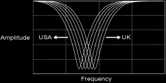
One of their most interesting innovations is their patented "ISF Control" ("ISF stands for Infinate Shape Feature") - a control which allows you to alter the position of the mid cut in a standard passive guitar amp tonestack:
Turn the ISF toward USA and you lower the frequency of the mids scoop, go towards UK and you raise it.
So, how on earth does that work? Firstly check out this video from Blackstar themselves:
A pretty impressive control in itself (not too sure about that demo at the end, not quite to my tastes!). So now we want to know how it works! Well, check out the actual patent application Blackstar made to the UK (Big shout to the UK based manufacturers :-) Patent Office:
So it's basically a dual ganged pot with each of it's individual pots added into a key location in the tonestack network:
Unfortunately we have no values presented in the Patent Application to play with. Luckily some clever fellow has pulled apart a Blackstar HT-5 which has an ISF control located in it's preamp section:
Part of the Blackstar HT-5 preamp - note the ISF control and the surprising amount of solid state semiconductors!
Granted not all the values are there but it does give a starting point at least. So if we start out with C1 = 470nF, C2 = 220nF, C3 = 220nF and C4 = 4.7nF, R4 = 1k what else do we need, well, quite a bit really. I have it on reliable information that the dual ganged ISF pot is a dual 10k linear pot. This is still enough to start playing with though - don't use it in any manner you're not supposed to though - remember that this is Patented technology and, as such, Blackstar has complete control over it, this article is just a quick look at one of the most interesting tone shaping ideas developed in recent years in the guitar amplification scene.
So, we've all played guitars with humbucking pickups right? The warm, chunky yet still cutting tone humbuckers can produce has lead to some of the greatest guitar tones in Rock 'n Roll. Just imagine; where would the world be with out Angus Young's signature humbucker equipped Gibson SG along with his sweet crunch tones and killer riffing on "Back in Black"? What would the Seventies have sounded like without Jimmy Page and his legendary Les Paul? Further more just imagine the grunge movement of the late Eighties and early Nineties without the searing, "wall of noise" created by Kurt Cobain's humbucker driven Fender Mustangs, Jaguars and Jagstangs?
Whether it's classic crunch or full on tonal meltdown you're looking for the Humbucker can get you there - with the added bonus of no "added" 60Hz hum that is associated with P90 and Single Coil pickups :-D
Jimmy Page of Led Zeppelin with his Humbucker equipped Les Paul
The Original - the Gibson P.A.F Humbucker
So what is a "humbucker" and where did the design original from?
By the early 1950's Gibson was being directly challenged by Fender as the major producer of quality solid body electric guitars, to counter the Fender charge on the market Gibson decided to develop a high quality, low noise pickup with which to equip their newly introduced "Les Paul" model guitar. Seth Lover was the engineer assigned with the task of developing this new product. In order to solve the inherent noise problems of the P90 and single coil pickups Lover decided upon connecting two side by side single coil pickups in series but with opposite magnetic polarities and opposite current travel in either coil. The product he developed changed the sound of electric guitar forever - the Humbucker was born!
Original "Zebra" P.A.F Humbuckers [2]
Gibson filed their patent for the pickup design on June 22, 1955. And by 1957 the humbucker was standard issue on most of Gibson's products. However - the patent wasn't fully granted until July 28, 1959. This led to Gibson sticking on the little black "Patent Applied For" decals on the back of those early humbuckers (from late '57 till mid/late '62) hence the "P.A.F" abbreviation. [2]
Original Gibson P.A.F humbuckers with black decal [2]
Here's another interesting piece of info regarding those early Gibson pickups:
"Seth Lover received his pickup patent #2,896,491 on July 28, 1959. By mid to late 1962, Gibson changed the pickup decal to read, "PATENT NO 2,737,842". Interestingly the patent number listed on the decal was not for Seth's pickup design but was for Les Paul's trapeze tailpiece! Perhaps this was a research roadblock for the competition, or maybe just a mistake?" [2]
And an extract from the actual humbucker patent granted to Seth Lover:
An extract of the original Humbucker Patent filed by Seth Lover
How do Humbuckers buck the hum?
Now we know where the original P.A.F came from I'll offer a quick explanation of how the technology works to give us a general idea of what is going on between those coils!
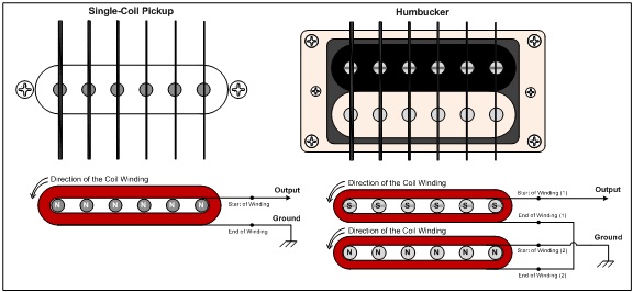
The image below shows how the humbucker pickup is laid out:
(fig.1) Basic Drawing of a Humbucker Pickup [3]
As you can see the two coils have opposite magnetic polarities; the top coil is "North" and the lower coil is "South" (in a regular humbucker the South pole coil is the one with adjustable screws, the North has non-adjustable metal slugs). Further more note the coil windings; they are both wound in a clockwise direction from their starts to finish but, and here's the key, look at the direction the current travels in each coil; in the North coil it travels in a clockwise direction from red to black yet in the South coil it travels in an anti-clockwise direction from the "series connection" (the point at which the two coils are electrically joined by the black and white wires) and the white wire through to the green wire. In a standard humbucker the red wire would be your "hot" or signal connection and the green would be the grounding wire (note that different humbucker manufacturers use different coloured wires so your connection wires won't always be red and green).
Single coils Vs Humbuckers
So, how does this configuration allow the humbucker to perform it's duties and "buck the hum" associated with it's single coil brothers? Well I turn to this handy explanation:
(with reference to fig.1) "Coil 1 and coil 2 are electrically out of phase and since electrical interference only travels through the guitar pickup's windings, when the hum travels from one coil to the other, it gets canceled due to the opposite coil windings. (The magnets play no part in hum cancelation.)
Unlike hum, an electric guitar's sound (the signal) is generated from the pickup's wiring and magnets. So, when the guitar signal travels through the coils, no cancelation occurs because the coils are out of phase electrically and magnetically.
In effect, having opposite electrical and magnetic polarities is similar to putting two phase switches on two pickups. When both switches are set to the out of phase positions, no cancelations occur because the 2 "out of phase" conditions cancel each other out." [3 - http://www.1728.org/guitar1b.htm]
Wikipedia (although I do dislike referencing wikipedia!) also has some useful info (al be it slightly incorrect - my edits in brackets []):
"In any magnetic pickup, a vibrating guitar string, magnetized by a fixed magnet within the pickup, induces an alternating voltage across its coil(s). However, wire coils also make excellent antennae and are therefore sensitive to electromagnetic interference caused by alternating magnetic fields from mains wiring (mains hum [60 Hz hum]) and electrical appliances like transformers, motors, and computer screens. Guitar pickups reproduce this noise, which can be quite audible, sounding like a constant hum or buzz.
The direction of a voltage induced across a coil by the moving string depends on both the coil winding direction and the direction of the fixed magnets. A humbucker has two coils wound in the [same direction but with opposite directions of current travel]. The magnets in the two coils are arranged in opposite directions so that the string motion induces voltages across both coils in the same direction. Electromagnetic interference, on the other hand, induces voltages in opposing directions across the coils because it is only sensitive to the winding direction. When the signals from both coils are summed together, usually by connecting the coils in series, the two noise voltages cancel, while the signal voltages add thus dramatically improving the signal-to-noise ratio."
[4 - http://en.wikipedia.org/wiki/Humbucker#How_humbuckers_work]
Still not sure what differentiates a single coil pickup from a humbucker? Check this video out:
Back to the P.A.F - Design considerations
Now, many guitarists go crazy for the original P.A.F tone, the original pickups sell for hundreds and examples of late 50s and early 60s Gibson guitars with P.A.F humbuckers sell for tens of thousands. Many of todays boutique pickup manufacturers offer a straight clone of the P.A.F and charge a healthy price for it. Below is a video of the (very nice!) Bare Knuckle Pickups "The Mule" which is a faithful reproduction of the original P.A.F:
So how were the originals made and what makes them sound the way they do? Firstly lets refresh ourselves with the humbucker and it's components, fig 2 shows you all the internal parts of the humbucker:
fig 2. Internal humbucker structure
As you can see from fig 2 there aren't a huge amount of parts involved in the construction of a humbucker. However the parts do need to be put together concisely, taking into account a number of key tonal factors to ensure a decent sounding pickup is produced. These tonal factors are wide ranging and cover all aspects of the pickup's design and construction and, indeed, many guitarists will insist that very strange factors (with no scientific or technical evidence to support their claims) will affect a pickup's tone (e.g - it was made on a Tuesday by "Ron" - it's all in the "mojo"). However, we're not interested in the far out theories on tonal excellence regarding the P.A.F humbuckers, we're interested in the *real* reasons the P.A.F humbuckers sound the way they do and these, with reference to various sources, are [5][6][7]:
Magnet type,
Wire quality, gauge and insulation,
Number of coil windings,
Baseplate and covering,
Overall coil shape,
Coil winding pattern, and
Potting.
Now, lets investigate each of these factor in more depth. Firstly;
The type of magnet that a humbucker uses is one of the most important factors in deciding it's overall tone. There are essentially two types of magnet that are widely used in humbucking pickups; ceramic and alnico (aluminium, nickel and cobalt alloy). The key factor in determining the tone that a magnet will impart upon a pick is it's overall magnetic strength. The strength of a magnet is noted by the number after it's material; the higher the number the higher the magnet strength. Ceramic magnets are more powerful than alnico and due to the increased cost of higher strength alnico magnets they are usually selected when you need more power than an alnico 5 magnet (although you will see Alnico 6 and 8 pickups about). So what difference does this increase in magnet power make to the tone of the humbucker? Generally the higher the strength of the magnet the more emphasis on the highs and upper mids, this usually sees higher strength magnets being described as "bright" and "brittle".
Humbuckers that utilise coils wound with a higher DC resistance and therefore a hotter output often use stronger magnets, and their increased high end response, to compensate for the inherent high end losses caused by the hotter coil windings.
Here's a concise description of the differences between alnico and ceramic from the GuitarTechCraig website:
"Alnico was used in all popular vintage pickups and generally has a warm and smooth response. Ceramic magnets tend to boost treble response and have become popular for pickups with extra coil winding to compensate for the treble loss. Alnico magnets also lend to a smoother distortion tone with a prominent midrange while ceramic magnets can improve the clarity and high end grind of a distorted tone. There are many different formulas of Alnico and Ceramic magnets. In general, the stronger the magnet can be magnetized, The brighter it will sound in a pickup." [9]
Furthermore, Tim, from Bare Knuckle Pickups, offers this more in depth break down and description of the various magnet types:
"Magnets do add to the character of a pickup although it must be understood that a magnet doesn't have a sound on it's own, it contributes by the way it accentuates certain frequencies as current is produced in the coil windings.
Alnico II is the softest and generally has a smooth bass and treble although this is more pronounced the hotter the windings get.
Alnico III is very transparent, low output and clean,sounds great for rounded fat jazz applications-typical of '50s tone.
Alnico IV is probably the best vintage tone IMHO(for humbuckers) and along with II and III was used in the earliest PAFs-this is a fact and not myth as we've had them analysed and a collegue of mine has also seen original Gibson purchase orders that clearly state AIV bar stock being purchased.The tone of AIV is balanced and extremely organic, it produces the most authentic vintage tone and sits better in slightly hotter vintage winds than AII which tends to get very soft in the bass and highs if used incorrectly.
Finally Alnico V is the hottest producing more highs and lows, great for rock applications or where power and cut are important.
Different companies use different grades for personal reasons, we use all of the applicable Alnico grades to suit the correct design, both to be historically correct but more importantly to have the best sound.
Changing magnets in a humbucker can give dramatic results, you soon find the ones that really don't sit right and others that are head and shoulders better........
[regarding ceramic magnets]
We use ceramic 8 as do most pickup makers-it is more powerful and essentially more efficient so the resulting tone usually has a very fast tracking bass response with a distinct cut in the highs.Some players find them cold/hard when run clean and they can cause alot of compression from their relatively hot output-again, depending on how you use them, they are capable of good clean tones too but the general consensus is that Alnicos are sweeter run clean." [10]
This Bare Knuckle Pickup's video provides and insight into the differences between ceramic and alnico magnets and gives you and idea of how magnet strength affects the overall tone of the humbucker:
So, there are the differences in magnet types. Getting back to the P.A.F; what did the original use? Well, inconsistency was king at Gibson in the late 50s and 60s and a range of magnets were used; Alnico 2, 3, 4 & 5. It is suspected that the majority of P.A.F era humbuckers utilized alnico 4 (IV) magnets as backed up by Tim from Bare Knuckle Pickups;
"Ask Gibson historian Walter Carter to look up the purchase orders for the mid to late '50s for magnet bar stock or ask Tom Holmes(ex Gibson) who's also seen the records which show Alnico IV bar stock being purchased during this period.The X ray spectrograph analysis showed a 1959 PAF humbucker magnet as being Alnico IV."
Tim also uses the Alnico 4 magnets in his "The Mule" P.A.F replica. This inconsistency in magnet type continued at Gibson right through the late 50s and early 60s, however by 1965 Gibson was using Alnico 5 magnets in all their humbuckers. [2]
You should also take into account the size of the magnet; "The original PAF magnet length was 2.5" long, which was decreased by 1/8" to 1/4" to around 2.25" in July 1961." [2]
And further more;
"Dimensions of PAF magnets follow (measured using a micrometer, and obviously this will vary a bit from magnet to magnet): 2.509" long ("long magnet" version), .506" wide, .131" thick. The "short magnet" PAF length was the a bit different: 2.371" long, .491" wide, and .121" thick." [2]
Wire Quality, Gauge and Insulation
Different wire types - note the plain enamel insulated and it's purple colour wire to the right.
Take this description from skguitar.com, which covers everything in general about humbucker wire selection:
"The finer the wire the fewer highs pass through. Finer wire also has a higher resistance for a given length. For this reason a pickup wound to 6k with 43awg [thinner] wire will have less output than a pickup wound to 6k using 42awg [thicker] wire. Regardless of what has been said I do no believe there is any difference based upon type of insulation alone. However, wire with a heavier insulation (i.e. "double build") will result in a wider coil at the same resistance/output [altering the coil shape alters the tone too].
There is a characteristic of wire called "skin effect" which is more pronounced in smaller diameter wires due to thier higher restance. "Skin effect" is where the higher frequencies travel along the surface of the wire rather than travel thru the center of the wire. This leads to that "brittle" characteristic of high output pickups which must be wound with the finer wires." [5]
As you can see the choice of insulation has no direct impact on the tone of a humbucker, it may, however, have an indirect impact on tone due to alterations in coil shape and thickness.
So, once again - back to the original P.A.F; what type of wire was used in their construction?
It is widely acknowledged that the original P.A.Fs were wound with 42AWG wire with a plain enamel (which gives it a purply colour);
"The pickups were wound with #42 plain enamel wire. On original PAFs the bobbin wire appears purple, versus later PAF and patent# pickups that appear reddish. Gibson eventually switched to polyurethane coated wire around 1963." [2]
Also note you want good quality wire that has a regular gauge without large fluctuations and without any voids associated with the tooling of wire. If you can get wire that has been annealed (heat treated to remove voids and defects associated with tooling) you're onto a winner!
Number of Coil Windings / DC Resistance
Winding a pickup bobbin
The more windings on a coil the higher it's DC resistance, inductance and output. A higher number of windings gives a more girthy, mid range dominated pickup while more highs are rolled off due to an increased coil inductance and capacitance. Take this explanation from the MusicalIlluminism blog;
"Fewer winds will have an audible effect, because the pickup will have less inductance, which affects the frequency response – making the pickup brighter. The pickup inductance interacts with the guitar volume/tone controls, guitar cable capacitance, and amplifier input load to create an EQ network. More inductance causes more highs to be lost in this EQ circuit."
So what are the specs on the vintage P.A.F?
"Due to the human factor and the wide tolerance of the manually-run pickup winding machines used by Gibson from 1956-1961, PAF pickups usually measure between 7.5 and 9.0 thousand ohms (K ohms). By 1962 (the end of the PAF era), Gibson was making pickups very consistently with 7.5k ohms of wire (give or take .25k ohms).
The separate bobbins of a PAF can measure very differently due to Gibson's manufacturing techniques. For example one bobbin could measure 3.5k, and the other 4.5k ohms (for a total of 8k ohms). This mis-matched ohms is actually a good thing, as certain frequencies will stand out if both bobbins have different resistance. This contributes to why two PAF pickups can sound quite different." [2]
As you can see there is a mention of mis-matched coils, usually humbuckers sound best if the the bridge humbucker has it's slug coil wound with a higher resistance than the screw side, this gives it slightly more mid grunt and avoids it becoming to treble heavy. For a neck pickup the opposite is true, with the screw side overwound the emphasis is more on the open strings of the neck and gives a more open and natural tone (the emphasis is on the part of the string that you want to hear!). [13] This is personal preference though and if you play about with which coil you offset you'll find your favourite. I'd try winding with offsets from a few hundred turns right up to a thousand turns (I, personally, usually go for about 250-300 turns offset). For further insight take this explanation into coil offsets from Tim, of Bare Knuckle Pickups;
"Coil offsets do effect mid range but not quite to the extremes you may think. What's actually happening is the moment there is asymmetry between the coils phase cancellation isn't 100% any more. Aurally this means more highs come through and the 'perception' of midrange alters.If I wound 2 coils with 5000 turns each they would be perfect humbuckers and cancel out 50/60 cycle hum efficiently. If I wound 5150 and 4850 which would produce almost the same DC reading, you'd hear high end which balances against the mid range giving the impression of it dropping back. As you're no doubt aware when you use a graphic EQ, altering the phase of one cycle tends to knock the phase of the others-how much is perceived and how much actual I wouldn't like to hazard a guess as it'd take some serious analysis to verify. Bottom line, anything to do with altering coil shape, size, no. of winds, offsets between coils etc will effect tone.
Before anyone panics about offset coil pickups not being 100% true humbuckers, panic not..........in my experience you can offset coils by as much as 1000 turns before noise becomes audible.This is dependant on wire gauge and overall no. of turns.................generally the offsets we use are nothing as extreme and no noise is audible at all." [14]
And here's another explaination of the offset effect from MDV over at the Bareknucklepickups Forum;
"The hum cancelling effect of humbuckers is a 1:1 turn per turn effect. Turns wound in the opposite direction and powered by magnetic fields going in the opposite direction (RPRW; reverse wound, reverse polarity) cancel the natural noise that each turn makes. That means that, as nolly alludes to, if wind is assymetric then the excess turns on one side behave as single coil turns because they dont have corresponding turns to cancel them, and have more top and more bottom, but noise is not cancelled. This gives more clarity and depth to the pickup (but mainly clarity/top end).
Its also true that the noise isnt noticable and bk offsets are well below whatever the offset threshold for noise is." [15]
With a little searching I found a few specs for Gibson "Burstbucker" Humbuckers (The Gibson replica of the original P.A.F) and their individual coil windings;
As you can see from these figures the offsets aren't huge; just enough to introduce a little play in the high frequencies. Remember - to much offset and you'll reintroduce 50/60Hz hum back into the pickup!
If you play with higher gain settings you may like both coils to be matched as closely as possible for a smoother more mid dominated humbucker.
Regarding the total DC resistance, you can see the original P.A.Fs vary between 7.5K and 9K. I wind my bridge humbuckers to 8.3-8.5K and my neck humbuckers to 7.3-7.5K. This gives a decent output in the bridge position that breaks up well yet still cleans up with the guitar volume control. The lower output in the neck position gives a more rounded, natural tone with the warmth associated with the neck position.
Baseplate and Covering
If the baseplate is metal and not grounded it will increase the inductance and capacitance of the humbucker, therefore rolling off more highs and adding lows and mids. The cover has the same effect. Now "early P.A.F. pickups as used on the 1956 lapsteels and 1957 Les Paul Standard had brushed stainless steel pickup covers (brushed to make them look nickel plated). This quickly changed to brass covers with a nickel plating. If the cover was gold, the brass was first nickel plated and then gold plated. Early PAFs also have four brass bobbin attachment screws, instead of steel screws." [2]
On pickups I've built I've always used Nickel Silver base plates and Nickel Silver covers and they've always sounded good. The difference between covered and uncovered humbuckers is illustrated nicely in this video:
You can hear the subtle differences - the slight increase in highs of an uncovered pickup versus the rolled off highs and increase in mids of the covered pickup. The choice is yours!
Overall Coil Shape
Short fat coil bobbins
Tall thin coil bobbins
"A coil which is taller and narrower will be clearer, more focused and slightly brighter than another coil which is shorter and wider if they have the same output. This is because the shorter wider pickup is sensing a wider section of the string, which gives it more variance in the signal it's sensing (due to variance in oscillation size/ pattern of the string along the length of string sensed)." [5]
Now, all humbucker bobbins are made a standard height, the only difference will be in the width of the coil. The use of a thicker gauge wire will increase the width of the coil, a lower or higher winding tension will also alter the shape of the coil as will the use of wire with thick insulation.
A well wound medium tension coil from 42AWG plain enamel insulated wire should produce the classic P.A.F coil shape; a full but not overwound bobbin.
Coil Winding Pattern
A pickup wound by machine will have a very regular and even wind pattern, a pickup wound "by hand" (i.e guided onto the bobbin by hand) will have a much less regular wind pattern - this is called "scatter winding" and many guitarists believe it gives a much superior tone when compared to regular machine wound pickups. Tim, of Bare Knuckle Pickups, scatter winds all of his pickups;
"Scatter-winding can only truly be done by hand and represents a high degree of skill by the person winding the coil. Although time consuming, it has many advantages over conventional machine winding and mass-production, not least the far superior tone and dynamics produced. We deliberately scatter the wire as we build up the windings of the coils so the wire isn't as even turn on turn, layer on layer, as with the more uniform wind of an automated machine with pre-tensioning. This lowers the distributed capacitance that exists between the turns of wire. Lower capacitance means improved high-end clarity, the resonant peak increases slightly and frequency response is greatly extended. The tension of the wire is also varied as it moves through the operator's fingers reflecting the ability to control the tension within the coil by the person winding the pickup. The result is a clearer, more open tone that has the impression of being louder purely by the amount of extra detail and dynamics present." [12]
The original P.A.Fs were machine wound but the use of scatter winding is certainly one way to improve upon the tone. Lets face it - if we're winding our own pickups they are going to be "scatter wound" unless we have access to a proper pickup winding machine.
Potting
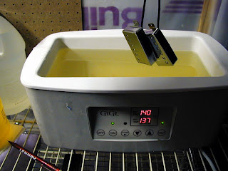
Potting humbuckers in wax
Potting involves dipping the finished pickups in wax or other similar materials (epoxy or lacquer) to solidfy the coil windings and remove unwanted microphonic feedback (those horrible squeals you sometimes get at high gain). The original Gibson P.A.F humbuckers were not potted but most modern reproductions are. I always pot the humbuckers I wind, it's a simple process (submerge the pickups for 10 mins in parafin wax at 65 degrees centigrade) and in my opinion the positives out weigh the negatives. But don't take my word for it. Once again with reference to Bare Knuckle Pickups;
"Unpotted coils have a very dynamic and touch-sensitive feel with a brighter edge which is well-suited to low gain playing, while potted coils have better feedback rejection and are much more practical for any playing style where high amounts of preamp gain and loud volume are used. We do make pickups with unpotted coils as an option, although we lacquer the magnet and use paper tape inside the cover to help reduce squealing, just as in the early humbuckers.
Historically, not all pickups were potted but with modern high gain amplifiers and performance this isn't always practical. Nearly all our finished coils are potted in a mixture of paraffin wax and bees wax to remove unwanted air trapped in the coil, solidify the windings and prevent microphonic feedback. All of our high gain models or any pickups that require metal covers are wax potted a second time to eliminate any chance of microphony." [12]
Once again, this choice is yours!
So there you have it; how humbuckers came about, how they work and how the various design considerations effect the overall tone that the humbucker will produce. Below are some specs for the various Gibson P.A.F era humbuckers.
Various Gibson P.A.F era Humbucker specs
"1956 – 1957 (“PAF”): Long (2.5”) Alnico 2, 3, 4 and 5 magnets used randomly, brushed stainless steel cover, *no* PAF sticker, automatic traverse wound with manual-stop (until bobbin was “full”), #42 plain enamel wire (purple/maroon), individual coil ohm differences, black leads on coils, ohms vary from low 7k to high 9k, black PAF-style bobbins (“square in circle” with holes). PAFs first installed on Gibson lap-steels in ‘56 and then guitars in ‘57.
1957 – 1961 (“PAF”): Long Alnico 2, 3, 4 and 5 used randomly (A2 most common), nickel cover, “Patent Applied For” sticker, automatic traverse-wound with manual-stop, #42 plain enamel wire (purple/maroon), individual coil ohm differences, black leads on both coils, ohms vary greatly – generally between 7k and 10k, black and cream (early-’59 thru mid-‘60), all bobbins black again by late ’60, PAF-style pickup bobbins.
1961 – 1962 (Late “PAF”): Smaller (2.37”) Alnico 5 magnet used for remaining production (all transitioned by July ’61), nickel cover, PAF sticker, automatic traverse-wound with manual-stop, #42 plain enamel wire (purple/maroon), black leads on both coils, individual coil ohm differences, ohms averaged 8.0k by ‘62, PAF-style bobbins." [11]